Flipdot Display
Untapped potential
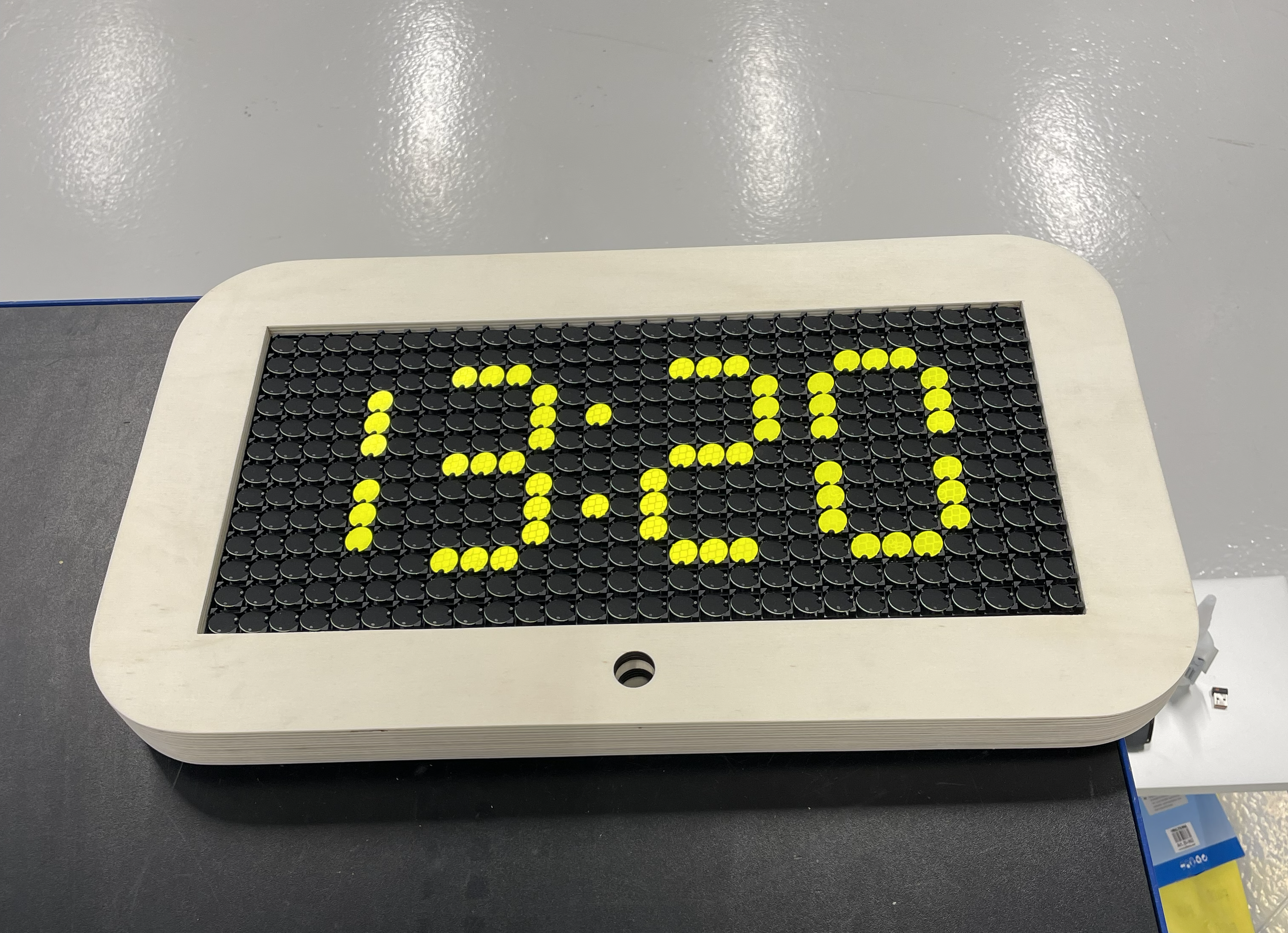
I got this display from a former colleague who had found it in a dumpster. It was basically just a large PCB with 13×28 flipdot pixels and some logic ICs — no enclosure, no documentation, no idea if it even worked. I thought it would be fun to see if I could bring it back to life and drive it from a microcontroller, either for animations or as a nice-looking wall clock. With zero knowledge of its state, I got to work reverse-engineering the board.
Reverse engineering
I sketched out the circuit and figured out which pins to wiggle to make the display do what I wanted. The panel seemed to be divided into four column sections and two row sections, where each section consists of a demux (74HC4514), a source driver (TD62789A) and a sink driver (ULN2003A). Together they decide which pixel gets a short current pulse, and the direction of that pulse decides whether the dot flips to yellow or black.
Once I understood the pattern I hooked a Raspberry Pi Pico to the display board's IDC connector and started poking around in CircuitPython to see if I could flip some pixels. After some fiddling I got the display running and could draw bitmaps and simple patterns on it. I also put together a simple Python program to emulate the panel on my computer, which made it much easier to see which fonts and layouts actually read well at 28×13 before pushing pixels to the hardware.
It quickly became clear, though, that CircuitPython wasn't quite suitable for this project. The GPIO layer simply isn't fast enough for the update rate I wanted, especially once you start thinking about smooth animations across all 364 pixels.
Custom driver
With CircuitPython's limitations in mind, and because I wanted a wireless connection to the display, I started designing a driver board around an ESP32. I picked the ESP32 Feather module since I had a few of those lying around at home. The driver board is fairly simple: an IDC connector matching the flipdot board, with a 1-to-1 IDC cable in between.
The original plan was to run the whole thing from a single-cell LiPo battery. The ESP32 Feather has built-in battery charging, and the display itself draws nothing between refreshes, so it seemed worth trying. The flipdot panel needs 24 V DC, which means boosting the cell's 3.7 V.
Once the board was delivered and assembled, I tried to feed it from a single LiPo cell but I got issues with voltage drops on the low voltage side. Flipping a pixel pulls a short but hefty current pulse on the 24 V side, and the boost had to source more current from the battery than the cell could deliver. I tried beefing up the 24 V side with capacitors, but then inrush when enabling the boost became a problem. That's solvable with more engineering, but I decided to move on: drop the battery, remove the boost converter, and feed the driver and display from a 24 V DC supply.
Here is the layout and the resulting board. Unfortunately, I forgot to take pictures of the final assembled board before it was mounted in the display frame.
Firmware
The display is driven by firmware (C-code) on the ESP32 with the esp-idf framework. It has a small layer that talks to the flipdot hardware and separate applications on top. A physical switch on the unit cycles between three modes: a wall clock, a demo screensaver that runs simple animations, and a games mode for anything that needs player input.
Clock mode keeps the panel useful as everyday decor. Demo mode loops lightweight visuals without any controller attached. Games mode is where interactive apps live; input arrives over ESP-NOW from a wireless controller I designed as a side project in a compact NES-style form factor.
Only Snake is implemented in the games slot so far, but the idea is to add more titles over time. Pong is next on the list as it would be nice to have a two player game. Switching modes clears the framebuffer and hands control to the next application, so each mode can run its own update loop without getting in the way of the others.
Here is a video of the display running the screensaver mode. Sound on for maximum pleasure!
Enclosure
I built the enclosure from 9 mm birch plywood sheets, stacked and glued into a single frame. Layering the cuts let me carve cavities so the flip-dot board and driver PCB sit in defined pockets instead of floating on standoffs. At the time I had access to a laser cutter that could handle 9 mm plywood, so this approach was the practical way to get accurate geometry without CNC milling the whole box.
I modelled everything in Fusion 360, exported the layer profiles, and had the sheets cut to match. Four layers make up the stack: I glued them together, sanded the outside until the edges read as one solid part, and finished with clear coat for a light sheen.
The assembly view below has the top sheet removed so you can see how the flip-dot panel and driver board nest inside the cavities. The grey block is the display module; the green PCB is the ESP32 driver sitting in its own pocket under the panel.
Once glued, sanded, and coated, the frame turned out nicely.
Final result
The display ended up mounted above a doorway at my office, where it runs as a wall clock most of the time. The birch frame fits the room better than a bare panel would, and the flip-dot noise is part of the charm when the time changes.
When the clock rolls into a new hour, the firmware runs a short full-panel animation before settling back on the time. Here it is crossing an hour boundary — sound on if you want the full flip-dot experience.